|
AVirtual
LAN also
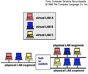
called a VLAN, is a logical subgroup within a
local area network that is created via software rather than
manually moving cables in the wiring closet. A VLAN acts like
an ordinary LAN, but connected devices don't have to be
physically connected to the same segment. It is a local area
network with a definition that maps workstations on some other
basis than geographic location (for example, by department,
type of user, or primary application).

While
clients and servers may be located anywhere on a network, they
are grouped together by VLAN technology, and broadcasts are
sent to devices within the VLAN.
Key
features of VLAN
The benefits of a VLAN include the ability to share
information and resources across locations as if they were all
under one roof. As a result of this, businesses can operate
more efficiently with improved productivity. Site-to-site VPN
is frequently used to implement VLAN with the added benefit of
strong security.
There
are two fundamental limitations of VLANS: performance and
management costs.
In
regard to performance, local area networks typically operate
at 100 Mbps with latencies of less than 5 ms. On the other
hand, wide area networks typically connect at 1.5 Mbps or less
with latencies averaging around 100 ms. So, a VLAN will not
perform as well as a local network. This is generally not a
problem, but can be if applications are chatty (i.e., send a
lot of small messages back and forth just to accomplish one
task) or require a lot of bandwidth (i.e., video streaming).
So, when designing a VLAN, one must take care to provision
enough bandwidth to accommodate the applications being
serviced.
In
regard to management costs: A VLAN is a wide area network and
typically requires additional security such as that provided
by IPsec and PKI. The need to support geographically dispersed
locations and extra security can increase overhead. Basically,
it's much more complex than connecting computers together in
the same building as would be the case with an ordinary LAN.
Standards
for VLANs
The standard 802.1q defines the operation of Virtual LAN (VLAN)
Bridges that permit the definition, operation and
administration of Virtual LAN topologies within a Bridged LAN
infrastructure. 802.1v is the proposed supplement that
will benefit users of multi-protocol LANs by permitting them
to specify VLAN structures suitable for each protocol present
in a LAN, and removing the need for a non-standard relay
function between VLANs.
-
Virtual LANs operate at layer 2 of the OSI model. However, a
VLAN is often configured to map directly to an IP network, or
subnet, which gives the appearance it is involved in layer 3.
-
This also means that if you tried to cascade your switches
hoping that the VLAN would work for both, then it would most
probably fail.
-
In order to cascade two switches together for a
VLAN, they
must support 'Trunk Links' where the above mentioned 'tags'
will be sent through a port of the first switch, into the port
of the second switch.
Security
in VLAN
VLANs
provide security in two ways:
-
High-security
users can be grouped into a VLAN, possibly on the same
physical segment, and no users outside of that VLAN can
communicate with them.
-
Because
VLANs are logical groups that behave like physically separate
entities, inter- VLAN communication is achieved through a
router. Thus, all the security and filtering functionality
that routers traditionally provide can be used.
VLANs function at layer 2. Since their purpose is to isolate
traffic within the VLAN, in order to bridge from one VLAN to
another, a router is required. The router works at the higher
layer 3 network protocol, which requires that network layer
segments are identified and coordinated with the VLANs. This
is a complicated job, and VLANs tend to break down as networks
expand and more routers are encountered. The industry is
working towards "virtual routing" solutions, which
allows the network manager to view the entire network as a
single routed entity.
Virtual
LANs solve the problem of containing traffic within workgroups
that are geographically dispersed. They allow moves, adds and
changes to be performed via software at a console rather than
manually changing cables in the wiring closet.
|
Layer
3: The network layer...This layer handles the routing of
the data (sending it in the right direction to the right
destination on outgoing transmissions and receiving
incoming transmissions at the packet level). The network
layer does routing and forwarding.
Layer
2: The data-link layer...This layer provides
synchronization for the physical level and does
bit-stuffing for strings of 1's in excess of 5. It
furnishes transmission protocol knowledge and
management.
|
|


